Ruichips Semiconductor is a national high-tech enterprise engaged in the research and development, production, and sales of silicon-based power semiconductors and digital analog hybrid ICs.
MORE +Ruichips MOSFET - RU30110L-B LED Dimmer Typical Applications
Ruichips MOSFET - RU30110L-B LED Dimmer Typical Applications
2024.06.05
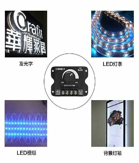
LED dimmer is a device used to adjust the brightness of lighting, widely used in households, commerce, and industrial fields. With the increasing emphasis on lighting environment comfort and energy conservation, the dimmer market has shown a steady growth trend in recent years. The principle is to control the brightness of LED lights by changing the voltage and current output from the DC power supply. The common principles of LED dimmers include PWM dimming and current dimming. PWM dimming controls the brightness of LEDs by constantly switching switches. The dimmer converts high-frequency alternating current into high-frequency square wave electrical signals, and controls the brightness of the LED by adjusting the duty cycle of the square wave. When the duty cycle is 100%, the LED light is at its maximum brightness, and when the duty cycle is 0%, the LED light is turned off.
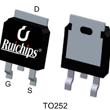
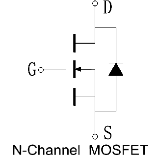
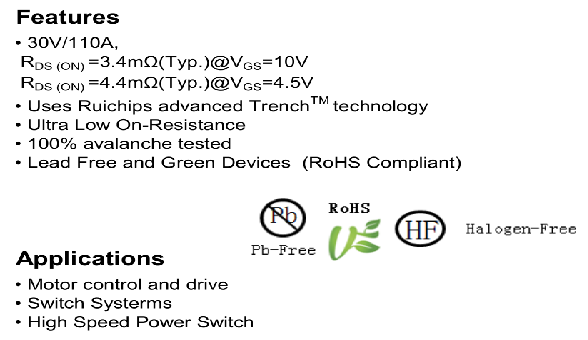
The Ruichips MOSFET RU30110L-B is widely and significantly used in LED dimmers, with advantages such as high efficiency, energy saving, reliability, and cost-effectiveness. It is an ideal choice in LED dimmer design.
Advantages and specifications of Ruichips RU30110L-B
Wiring diagram of LED dimmer
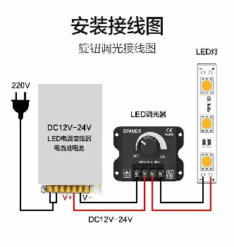
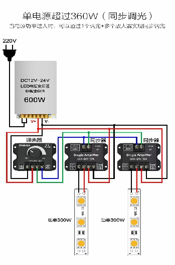
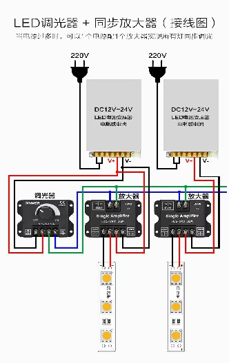
PWM dimming principle
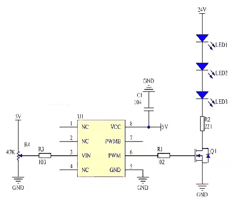
Dimming process
The input analog signal is a 5V potentiometer, connected to the VIN pin of the U1 chip through resistor R3. The PWM signal output by the U1 chip is controlled by resistor R1 to control the MOSFET, which drives three LED lights.
Through this circuit, the dimming function of LED lights can be achieved. Slide the position of the potentiometer and adjust it upwards. As the input analog voltage increases, the duty cycle of the output PWM signal increases, and the LED light turns on.
When adjusted downwards, the input analog voltage decreases, which , reduces the duty cycle of the output PWM signal, and the LED lights become dim.
If the Pin 7 of the chip is connected to an LED circuit identical to the Pin 6, two sets of LED dimming circuits can be obtained.
Contact Us
If you are interested in our products, please leave your email and we will contact you as soon as possible. Thank you very much.


